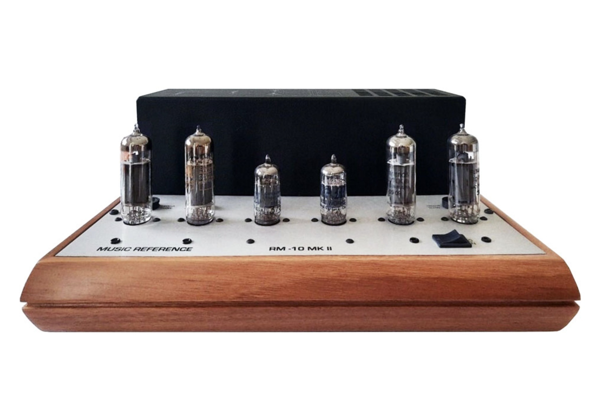
Roger is taking a break, so I am covering this edition of Roger’s Corner solo, and our topic is the Music Reference RM-10 amplifier. Now, why you may ask, would we talk about an amplifier the design of which dates back 30+ years, is no longer made, and barely shows up on the used market, making it difficult to obtain? The answer is simple, the Music Reference RM-10 MkIII is on the horizon. So, I thought now might be the time to talk about the design philosophy of the amplifier. As the RM-10 is unique among its peers, the story will be told in multiple parts.
Use of the EL-84 tube in an audio circuit dates back decades. The tube itself was released in 1953 and soon thereafter in 1954 the Mullard 5-10 amplifier appeared. This amplifier used two EL-84 output pentodes in a cathode-biased, push-pull circuit achieving 10 watts, 5 per channel, hence ‘5-10’. As the EL-84 became more popular designs using a pair of tubes per channel appeared. Some examples from the mid 1950s to early 1960s include:
-
Fisher SA-16 (15 watts)
- Pilot 232 (17 watts)
- Eico HF-14 (14 watts, 28 watts peak output)
- Acrosound 20-20 (18 watts)
However, in the opinion of many, the most famous vintage EL-84 amplifier was the Dynaco ST-35 released in 1963. This amplifier also used a pair of EL-84 per channel and outputted 35 watts continuous power, 45 watts music power, and 17.5 watts per channel. Ed Laurent designed the ST-35 and while very good in stock form this amplifier became popular with the DIY crowd as there were several upgrade kits designed for it to enhance its performance and reliability.
Moving on to modern times, a couple of popular EL-84 amplifiers include:
-
Audio Note OTO (single ended and push-pull versions, 10 and 9 watts respectively)
- Leben 300XS (15 watts)
While the amplifiers previously mentioned are by no means a comprehensive list, the industry standard is that a pair of EL-84 per channel in pentode tends to produce between 14 and 18 watts. So, how was it that Roger was the first designer to get 35 watts out of a pair of EL-84 tubes? To answer that question, we must refer to tube manuals where one could research tubes and circuit applications. The RCA Receiving Tube Manual is just one example. Here one can find an application for an EL-84 amplifier circuit that produced about 17 watts using a pair of EL-84 per channel. It is this application (and similar applications from other manuals) that designers referenced when developing circuits and why we see the consistency in power ratings.
Since Roger was a researcher, he studied the physical and electrical characteristics of vacuum tubes for years. While he referenced the circuit applications in the tube manuals, Roger also went outside the box and developed his own applications. He ran numerous simulations and proof of concepts with the EL-84, many of which failed. Ultimately the research and testing paid off as Roger validated that he could safely and reliably get 35 watts per channel out of a pair of EL-84 tubes. I can only imagine how many EL-84s gave their lives in this valiant effort.
So how did Roger do it? Well, the simple answer is that he employed a voltage doubler in the circuit that put 700 volts on the plates. Now some of you who are knowledgeable about tubes and audio circuits might scoff and say it is not possible when the tube manuals and data sheets specified 350 volts on the plates. The tubes will “red plate” and die a rapid and painful death. Well, the tube manuals only provided examples to give circuit designers something to work from. In Roger’s case it was the additional research and his ingenuity that took the plate voltage specification for an EL-84 tube to another level.
Besides doubling the plate voltage, there was another important aspect of the circuit that made all this possible. Again, all of you familiar with audio circuits take note here. As Roger proved, the EL-84 was more than capable of handling additional plate voltage and there are hundreds of RM-10 amplifiers out there that are a testament to this. The secret was maintaining 350 volts on the screen grid. That is where 700 volts would be a major problem. So, while that nifty voltage doubler passed 700 volts to the plates, the circuit was designed to ensure only 350 volts would be on the screen grid. That is how Roger was able to reliably get 35 watts out of a pair of EL-84 tubes without compromising tube life and performance.
I will stop here for now and let you all digest this, but will be back next month with more. So, if Part One of the story about the RM-10, or as I often refer to it, “the little amplifier that could,” piqued your interest stay tuned for Part Two when we will learn more about this little gem.